The COFLP Architecture Framework
Contextual - Operational - Functional - Logical - Physical
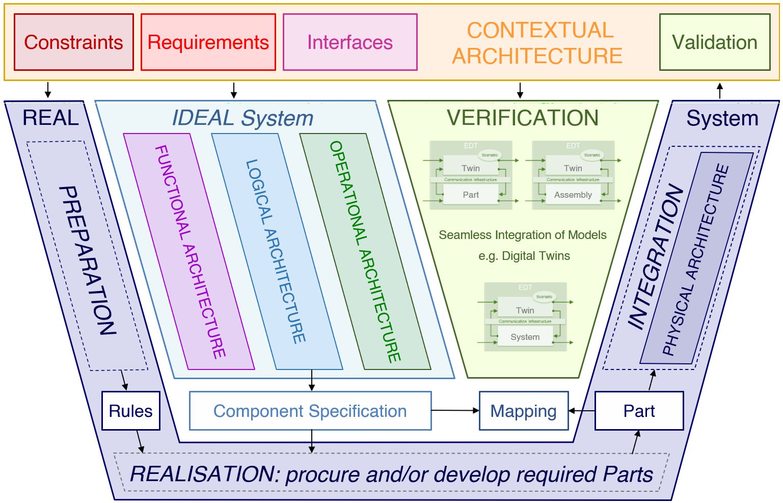
COFLP [ˈkɒpflɒp] is a Vee-Model Framework defining 5 Architectures: Contextual, Operational, Functional, Logical, and Physical. They each represent only one aspect relevant to System development and are strictly separated and thus orthogonal to one another (separation of concerns).
|
As illustrated, the COFLP clearly separates
It also deliberately limits the number of artefacts between the Ideal and the Real System. This shall prevent - to a large extent - that the Systems Architects write Domain requirements, and that Design details dominate discussions on Architecting issues. |
Each Architecture is developed using just one diagram type. Each diagram must only contain elements from the corresponding architecture, with the exception of the Logical Architecture, which combines elements from the Functional and Operational Architectures. All Architectures are, however, connected through the underlying Semantic Graph, which defines their relationships (e.g. the 'Component Spec' item between the Ideal and the Real System). In ADEPT, each Architecture allows for Variant modelling, includes the Decision-Making log complete with rationales, and can be annotated to aid long-term understanding of the Model.
Contextual Architecture
The Contextual Architecture is the robust definition of your Challenge. It is the result of an effective Context Analysis based on structured Requirements elicitation. For this, the relationships of all Stakeholders to the challenge are diligently analysed, additional Stakeholders identified, Assumptions recorded, Interfaces specified, potential Hazards collected etc. The Needs are analysed and 'translated' into Functional Requirements.
A good Contextual Architecture represents the Customer Needs, Requirements, Preferences and Constraints. The Requirements can be functional (Capabilities & Scenarios), Non-Functional ('-ilities'), or defining Interface properties.
Operational Architecture
The Operational Architecture is the principal Architecture for explicit decision making, comparing data, and interpreting information. It is made up of Operations, Control Flows that can also carry information (Data Flows), and Boolean Operators that define the logic, i.e. the order of execution. An important aspect of this Architecture is its capability to explicitly discussing potential failure and identify alternative or additional (clean-up or follow-up) Flows that might then be required.
A good Operational Architecture can be used as basis for developing the Control Unit of the System (like a blueprint for a Computer Program)!
Functional Architecture
The Functional Architecture comprises Functions, Object Flows and Objects. It represents the Flow of actual, physical Objects through the System and shows what Flows are required, which are generated where and consumed by whom. In this Architecture, you analyse Functions to find their lower-level Functions until reaching an “atomic” level, i.e. that level where you are confident that a physical mechanism or technical solution exists that can be used to realise the Function.
A good Functional Architecture is so much more than a 'Functional breakdown'!
Logical Architecture
The Logical Architecture defines the “breakdown” of the System into lower-level Elements, i.e. Sub-Systems and Components. The Objectives for the allocation of Sub-Systems and Components are to
- identify the System Elements that are potential solutions to a design implementing the Operational and Functional Architectures;
- Analyse these elements to either define Sub-Systems as new SOI in their own right or specify components that can be treated as “Black-Boxes” and sourced through acquisition, development or reuse;
- study variants and define trade-off criteria and weighting; and
- minimise the number of Interfaces between the System Elements, especially avoiding overloads and feedback.
A good Logical Architecture creates the Functional and Operational Interfaces and does not have to identify them later!
Physical Architecture
The Physical Architecture is by definition a tree structure, i.e. the Real System's breakdown structure. However, in the ADEPT process the development of this Architecture aims to provide 2 additional functions:
- The responsible for Ideal System Development provides the responsible for System Integration with Information about all dependencies between the parts and the components they map to (i.e. the "invisible" Interfaces). The Integration Strategy must be based on this information to prepare for functional testing of modules and parts.
- The responsible for System Integration defines Functional Zones within the Real System that define their purpose. This information has to be shared with the responsible for Ideal System Development, as it might influence the allocation of Functions and Operations to Sub-Systems and Components.
Accordingly, the Physical Diagram is NOT a breakdown structure, as this is created in the CAD model anyway. It visualises the mapping of Parts to Components complete with the Logical Interfaces between them.
A good Physical Architecture is the basis for successful Integration and Verification!