The ADEPT Architecting Process
Iterative, Recursive, and Modular
The ADEPT Architecting Process is a universally applicable step-by-step approach to developing good Systems Architectures. It is iterative and recursive and can be applied top-down, middle-out or bottom-up (e.g. for Reverse Architecting).
The following process steps are listed for a top-down approach:
Use Systems Thinking
|
This is not really a step in the process, but a general recommendation: make sure you understand why the challenge is relevant and why it landed with you Do write a Problem Statement about
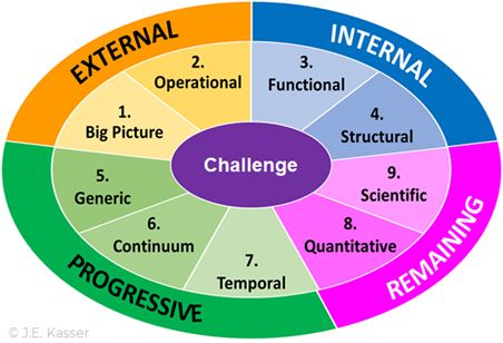
Employ Systems Thinking to probe deeper into the challenge and to better structure your understanding of it. Use the 9 Holistic Thinking Perspectives by Joe Kasser and Tim Mackley to further develop that structure. |
Analyse the Challenge
|
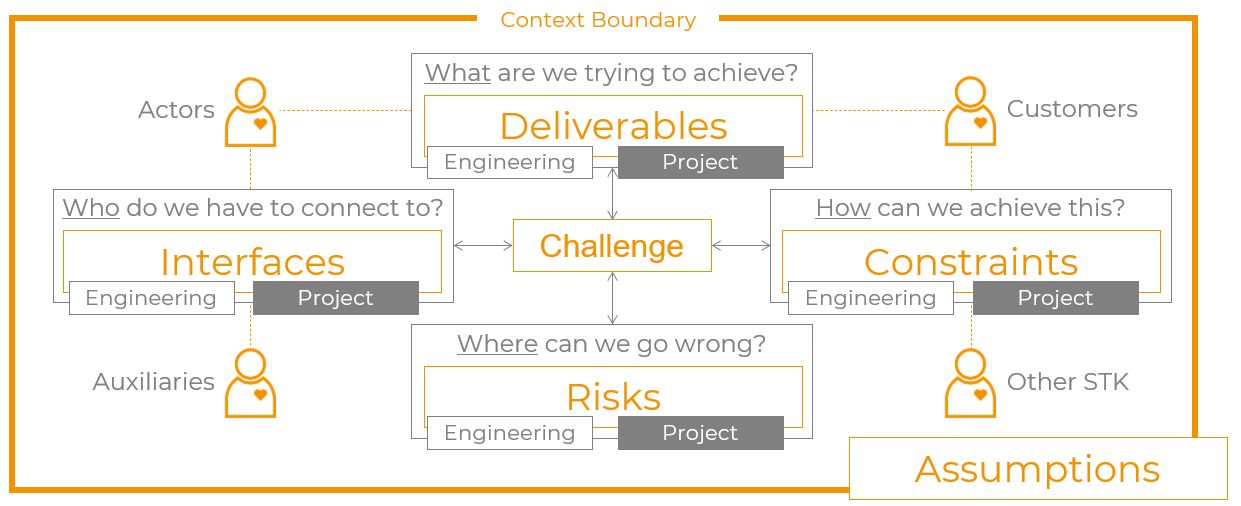
NOTE: you have to do this regardless, as it allows you to find out how much SE is needed. Verify you understanding of the project and engineering aspects. Identify for both aspects:
|
Categorise the Challenge

|
NOTE: from the context analysis, you should get enough information to perform this task. Some tips:
|
Structured Requirements Elicitation
|
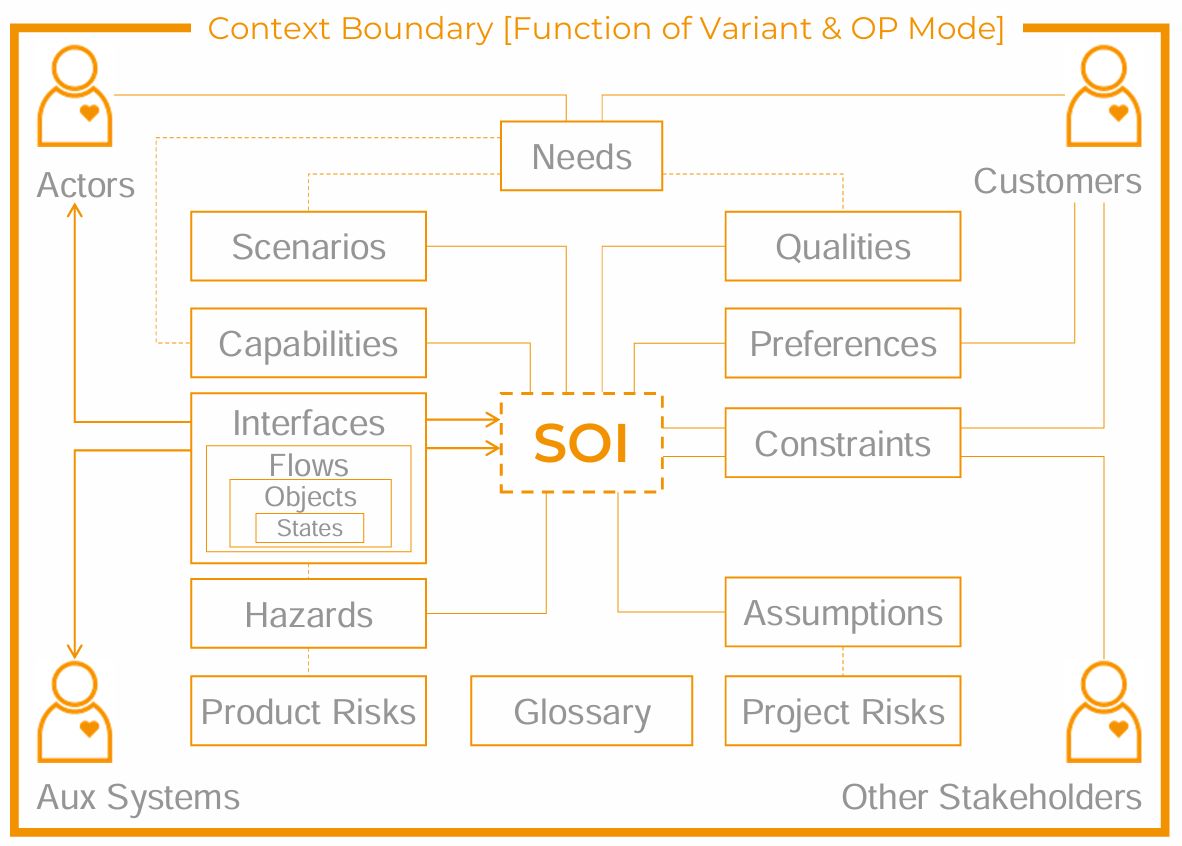
NOTE: The diagran is static. Each box is a register to be filled. The steps are:
|
From the Registers you can the derive the Customer Requirements (ReqC). Note, that in ADEPT, the ReqC are not the ones you receive from the Customer, but a set of formal Requirements that you must agree with the Customer. Make sure to take all Assumptions made back to the associated Stakeholders for Verification!
They typically comprise the following Elements:
- Scenarios (top-level Operational REQs)
- Capabilities (top-level Functional REQs)
- Qualities (top-level Non-Functional REQs)
- Interfaces (Object Flows, complete with Object properties)
- Constraints
Some Notes on Modelling
All modelling is an iterative and recursive process. However, in ADEPT, the Operational and Functional Analysis, yielding the Operational and Functional Architectures, respectively, are the natural starting point for developing the System Behaviour (which is typically what the customer pays for).
Each Diagram of the Architecture represents an element that contains lower-level elements of the same type. Each of these can then be further analysed in a new Diagram (hierarchical analysis).
Here is some general advice:
- always start from the “Sunshine Version”
- use the “pull principle” (i.e. start at the end, here the expected Flow)
- capture all assumptions and decision with the discussion that has gone into the Model
Develop the Operational Architecture
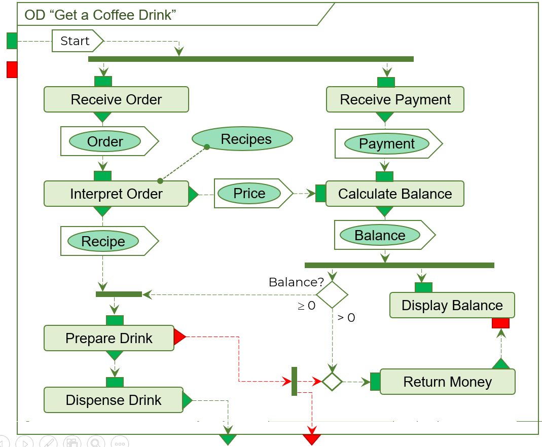
This is the principal Architecture for explicit Decision Making, comparing Data, and interpreting Information. It therefore can become the blue print for developing the Control Unit of the SOI.
|
NOTE: The separation of Operations and Functions (see below) allows you to identify all required operations without any notion of their functional implementation. Define top-level Scenarios using Sequence Diagrams or similar tools. The steps are:
|
Develop the Functional Architecture
Functions are “stupid”, i.e. they cannot make logical decisions. They are controlled by the Operations and provide them with the Signals required for their execution.
To develop the Functional Diagrams you best start from the expected Object Flows that are generated by the Function.
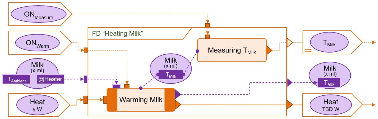
|
Here is some advice for the process:
|
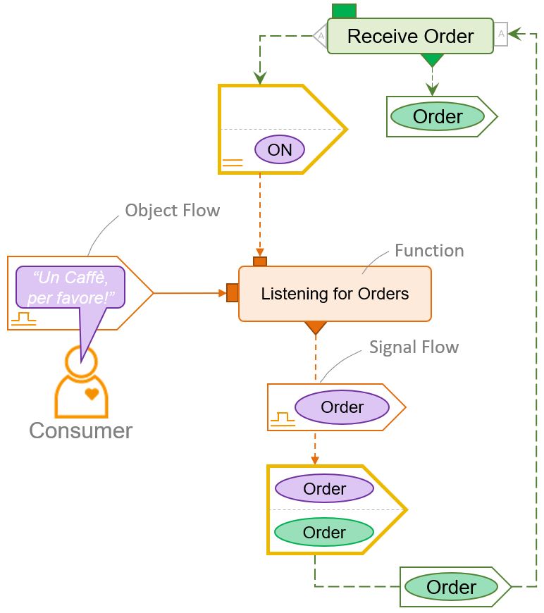
Connect Operations to Functions
|
Functions must never be part of an Operational Diagram and vice-versa. Instead, they are 'connected' by a Signal Exchange, which acts as a reminder that at some point in the development, the two Flows exchanged have to meet and be converted. Some Functions need Operations to tell them when to start and when to stop. And some Operations need Functions to provide information about the physical aspects of the System, e.g. what State a particular Part or Object is in. As the (abstract) Operational Architecture cannot directly generate or consume a (physical) Signal, they have to be converted from a Physical Object (e.g. pressing a button to open a door) to the related Data Object meaning (“Open door“). However, there is no clear rule who does the conversion. Instead COFLP provides a dedicated model element, the Signal Exchange. It allows to connect the flows between the two Architectures, without belonging to either. |
Develop the Logical Architecture
The Logical Architecture defines, how the System is broken down into lower-level elements, Sub-Systems or Components.
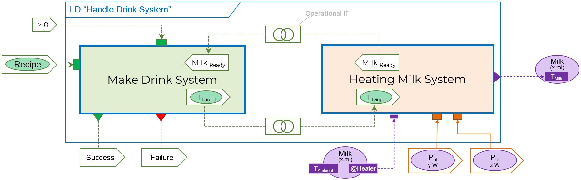
|
Its objective is to:
A System can be broken down by several logical aspects - hence the name! |
Component Specifications and Part Mapping

|
Components are specified in order to source physical parts for them
|
Develop the Physical Architecture
|
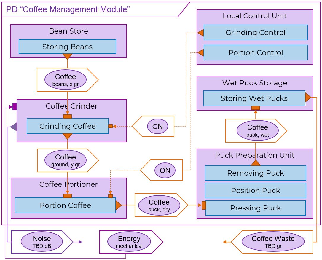
The Physical Architecture presents the final architectural model of all the physical units (Parts and Modules) with additional technical information, i.e. their Logical Relationships including the Functional and Control Flows, to allow for an understanding of their higher-level dependencies. Arrange the physical units such that it gives guidance for System Integration. Make sure that
For some of the Parts, new Flows emerge. This is particularly prevalent for electric power supply and additional external Flows, e.g. the noise made by some of the chosen Parts. |